


1. Struktur Pompa Sentrifugal Penggerak Magnetik Logam
Pompa sentrifugal penggerak magnetik terdiri dari empat komponen utama: rumah pompa, rotor, bagian penghubung, dan sistem transmisi. Pompa ini tersedia dalam dua konfigurasi: kopling langsung dan kopling tidak langsung. Desain kopling langsung memiliki kopling magnetik (magnet eksternal) yang terhubung langsung ke poros motor, sehingga menghilangkan kebutuhan akan poros eksternal, bantalan gelinding, atau komponen kopling, seperti yang diilustrasikan pada Gambar 1-12.
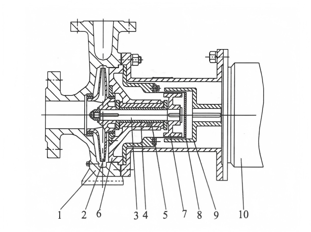
1—Badan pompa; 2—Impeller; 3—Poros pompa; 4—Selongsong poros; 5—Bantalan geser; 6—Penutup pompa; 7—Rotor magnetik dalam; 8—Selongsong isolasi; 9—Rotor magnetik luar; 10—Motor listrik
Pompa sentrifugal penggerak magnetik non-terhubung langsung, juga dikenal sebagai pompa sentrifugal penggerak magnetik standar, memiliki poros eksternal dengan kopling magnetik (magnet eksternal) yang terhubung ke motor melalui rumah bantalan dan kopling. Struktur skematik pompa ini diilustrasikan pada Gambar 1-21.
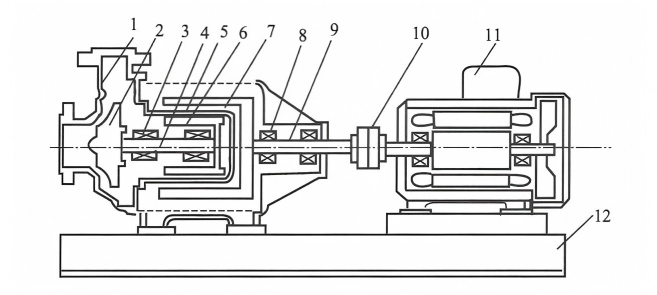
Gambar 1-21 Diagram Skematik Pompa Sentrifugal Penggerak Magnetik Non-Terhubung Langsung (Tipe Standar)
1—Badan pompa (wadah pompa); 2—Impeller; 3—Bantalan geser; 4—Poros pompa bagian dalam; 5—Selongsong isolasi; 6—Baja magnetik bagian dalam; 7—Baja magnetik bagian luar; 8—Bantalan gelinding; 9—Poros pompa bagian luar; 10—Kopling; 11—Motor listrik; 12—Dasar
(1) Bagian cangkang
Bagian cangkang terdiri dari badan pompa (cangkang pompa), penutup pompa, selongsong isolasi, dll. Bagian ini menanggung seluruh tekanan kerja pompa.
(2) Bagian rotor
Rakitan rotor terdiri dari dua komponen utama: bagian yang berputar yang dipasang pada poros pompa dan bagian yang dipasang pada poros penggerak. Komponen berputar pada poros pompa meliputi impeler, bantalan, rakitan cincin dorong, rotor magnetik bagian dalam, dan poros itu sendiri, yang membentuk bagian rotor yang berinteraksi dengan media. Bagian yang berputar pada poros penggerak terdiri dari rotor magnetik bagian luar, bantalan gelinding, selongsong poros penggerak, dan poros itu sendiri, yang membentuk bagian rotor yang bersentuhan dengan udara.
(3) Bagian penghubung
Struktur ini terdiri dari rangka penghubung, kotak bantalan, dan bagian-bagian lain yang berperan sebagai penghubung dan penopang.
(4) Bagian transmisi
Bagian sambungan mengacu pada kopling antara pompa dan unit penggerak. Pompa sentrifugal penggerak magnetik menggunakan dua metode sambungan: (1) menghubungkan kopling magnetik internal pompa ke kopling magnetik unit penggerak (kopling magnetik eksternal); (2) menggunakan komponen kopling ekstensi tipe diafragma untuk menghubungkan kopling magnetik poros eksternal pompa ke unit penggerak. Desain ini memungkinkan perawatan pompa hanya dengan melepas baut bagian tengah kopling dan diafragma, sehingga menghilangkan kebutuhan untuk membongkar unit penggerak untuk perawatan, dan dengan demikian memastikan perawatan yang mudah.
2. Komponen Utama dan Fungsinya pada Pompa Sentrifugal Penggerak Magnetik Logam
(1) Komponen Utama Pompa Sentrifugal Penggerak Magnetik Logam
Komponen utama pompa sentrifugal penggerak magnetik logam meliputi: impeler, poros, ruang hisap, badan pompa (rumah), selongsong isolasi, rumah bantalan, dan cincin port. Beberapa model mungkin juga menyertakan sudu pemandu, roda induksi, dan cakram penyeimbang. Saluran aliran terdiri dari ruang hisap, badan pompa (rumah), dan impeler, yang masing-masing memiliki fungsi sebagai berikut.
① Ruang masuk Ruang masuk terletak di ujung depan saluran masuk impeler, tempat cairan ditarik ke dalam impeler melalui lubang hisap. Diperlukan agar kehilangan aliran cairan yang melewati ruang masuk seminimal mungkin, dan kecepatan cairan yang masuk ke impeler harus terdistribusi secara merata.
② Impeller Impeller yang berputar mengubah energi dengan menarik cairan, memberikan energi tekanan dan energi kinetik ke cairan. Impeller diperlukan untuk memaksimalkan transfer energi ke cairan sekaligus meminimalkan kehilangan aliran.
(2) Fungsi Komponen Utama pada Pompa Sentrifugal Penggerak Logam-Magnetik
① Badan pompa (rumah pompa)
Badan pompa, juga dikenal sebagai selubung pompa, terdiri dari dua jenis: terbelah secara aksial dan terbelah secara radial, berfungsi sebagai komponen yang menahan tekanan cairan. Sebagian besar pompa satu tahap memiliki selubung volute, sedangkan pompa multi-tahap biasanya menggunakan selubung annular atau melingkar. Fungsi utamanya adalah untuk menampung cairan dalam ruang yang ditentukan, menyalurkan cairan yang dikeluarkan dari saluran aliran impeler ke pipa pembuangan, dan mengubah sebagian energi kinetik cairan menjadi energi tekanan, sehingga meningkatkan tekanannya.
Badan pompa umumnya memiliki tiga tipe berikut:
a. Badan pompa volute (cangkang) menyerupai cangkang siput (Gambar 1-22). Di dalam volute, terdapat saluran aliran dengan penampang yang melebar secara bertahap. Bentuk dan dimensi saluran-saluran ini sangat memengaruhi kinerja pompa.
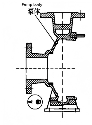
Gambar 1-22 Badan Pompa Volute
(Panah menunjuk ke lorong spiral dengan penampang yang tidak sama)
b. Badan pompa (rumah) dengan rakitan sudu pemandu. Badan pompa (rumah) adalah struktur berputar yang menampung komponen luar impeler.
Saluran aliran tersebut dikelilingi oleh beberapa struktur baling-baling pengarah.
c. Badan pompa (cangkang) berlapis ganda Badan pompa (cangkang) dengan selubung luar silindris tambahan disebut badan pompa (cangkang) berlapis ganda.
② impeller
Impeller, komponen kunci dari sebuah pompa, menggerakkan transfer cairan melalui rotasi kecepatan tinggi. Biasanya terdiri dari tiga bagian—hub, bilah, dan pelat penutup—impeller memiliki dua jenis pelat penutup: pelat penutup depan di sisi masuk dan pelat penutup belakang di sisi yang berlawanan.
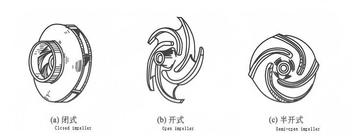
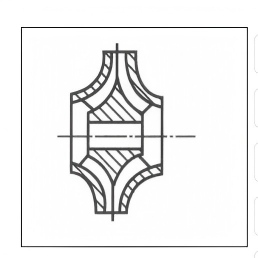
Pompa sentrifugal penggerak magnetik mengalirkan cairan terutama melalui aksi impeler yang terpasang di dalam badan pompa. Ukuran, bentuk, dan presisi pembuatan impeler sangat memengaruhi kinerja pompa. Berdasarkan konfigurasi struktural, impeler dapat diklasifikasikan menjadi tiga jenis: tertutup, terbuka, dan semi-terbuka (Gambar 1-23).
a. impeler tertutup
Impeller cakram biasanya terdiri dari pelat penutup, bilah, dan hub. Pelat penutup depan terletak di sisi hisap, sedangkan pelat penutup belakang berada di sisi yang berlawanan, dengan bilah-bilah ditempatkan di antara keduanya. Terdapat 4 hingga 6 bilah di antara kedua pelat penutup, dan bilah-bilah ini umumnya melengkung ke belakang, seperti yang ditunjukkan pada Gambar 1-23(a). Impeller tertutup sangat efisien dan banyak digunakan, terutama untuk mengalirkan cairan bersih tanpa partikel padat atau serat. Impeller ini tersedia dalam dua jenis: hisap tunggal dan hisap ganda. Impeller hisap ganda, seperti yang diilustrasikan pada Gambar 1-24, cocok untuk pompa aliran tinggi dan menawarkan ketahanan kavitasi yang lebih baik.
b. impeller terbuka
Impeller ini tidak memiliki pelat penutup di kedua sisinya, dengan bilah-bilah yang terhubung ke hub melalui penguat, seperti yang ditunjukkan pada Gambar 1-23(b). Desain impeller ini sederhana dan mudah diproduksi, tetapi memiliki efisiensi rendah, sehingga cocok untuk mengangkut cairan dengan kandungan zat padat tersuspensi atau serat yang tinggi.
c. impeller tipe semi tertutup
Impeller ini hanya memiliki pelat penutup belakang, seperti yang ditunjukkan pada Gambar 1-23(c). Impeller ini dirancang untuk mengangkut cairan yang rentan terhadap sedimentasi atau mengandung zat padat tersuspensi, dengan efisiensi yang berada di antara impeller terbuka dan tertutup.
Ada dua jenis bilah impeler untuk pompa sentrifugal: bilah lurus dan bilah bengkok.
Bilah lurus adalah bilah yang seluruh lebarnya sejajar dengan poros impeler, seperti yang diilustrasikan pada Gambar 1-23.
Bilah yang dipelintir memiliki bagian yang menyimpang dari sumbu impeler, seperti yang diilustrasikan pada Gambar 1-25. Untuk impeler dengan kecepatan spesifik rendah, bilahnya berbentuk lingkaran dengan saluran aliran yang sempit, sehingga memudahkan proses manufaktur. Sebaliknya, impeler dengan kecepatan spesifik tinggi menggunakan saluran aliran yang lebih lebar, sehingga memudahkan pelintiran. Bilah seperti itu meningkatkan ketahanan pompa terhadap kavitasi, mengurangi kehilangan akibat benturan, dan pada akhirnya meningkatkan efisiensi keseluruhan.
Ketika arah tekukan bilah berlawanan dengan arah putaran impeler, maka disebut bilah lengkung ke belakang; sebaliknya, disebut bilah lengkung ke depan. Karena efisiensi bilah lengkung ke belakang yang lebih tinggi, bilah ini umumnya digunakan untuk impeler.
③ choma
Cincin penyegel, juga dikenal sebagai gland, biasanya dipasang pada badan pompa dan membentuk celah minimal dengan keliling luar saluran masuk hisap impeler (Gambar 1-26). Karena tekanan cairan di dalam badan pompa melebihi tekanan saluran masuk hisap, cairan cenderung mengalir menuju saluran masuk hisap impeler. Fungsi utama cincin penyegel adalah untuk mencegah kebocoran cairan antara impeler dan badan pompa. Selain itu, cincin ini berfungsi sebagai komponen penahan gesekan. Ketika terjadi keausan berlebihan pada celah tersebut, penggantian cincin penyegel mencegah impeler dan badan pompa dibuang, sehingga memperpanjang masa pakainya. Akibatnya, cincin penyegel diklasifikasikan sebagai komponen pompa yang rentan aus. Dimensi celah antara cincin penyegel dan keliling luar saluran masuk hisap impeler umumnya ditentukan oleh diameter gland impeler.
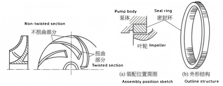
Gambar 1-25 Impeller dengan Bilah Terpilin Gambar 1-26 Diagram Skematik dariCincin Aus (Cincin Segel)
④ Selongsong isolasi
Dalam penggerak magnetik pompa sentrifugalPada pompa sentrifugal konvensional, selongsong isolasi terutama berfungsi sebagai segel poros, sebagai satu-satunya komponen yang memastikan pengoperasian anti bocor. Tidak seperti pompa sentrifugal konvensional, poros yang berputar tidak menonjol keluar dari rumah pompa yang diam. Sebaliknya, selongsong isolasi menggantikan segel poros tradisional, secara efektif mencegah kebocoran fluida bertekanan tinggi dan masuknya udara ke dalam ruang pompa (seperti yang diilustrasikan pada Gambar 1-27). Alasan desain ini menjelaskan dimasukkannya mekanisme penyegelan pada pompa tersebut. Poros dan rumah pompa dipisahkan secara fisik oleh selongsong isolasi, yang menggantikan rakitan segel poros konvensional.
⑤ Kopling Magnetik
Kopling magnetik terdiri dari magnet dalam (yang dilengkapi dengan dudukan magnet dan selongsong magnet) dan magnet luar (dengan dudukan magnet). Selongsong isolasi, yang terletak di antara magnet dalam dan luar (Gambar 1-28), merupakan fitur pembeda utama pompa magnetik dan berfungsi sebagai komponen intinya. Struktur kopling magnetik, desain rangkaian magnetik, dan pemilihan material komponennya secara langsung memengaruhi keandalan pompa, efisiensi penggerak magnetik, dan masa pakainya.
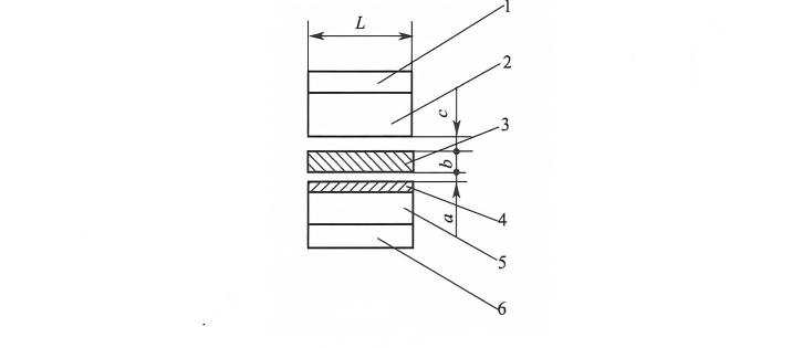
Gambar 1-28 Diagram Skematik Struktur Kopling Magnetik
1—Basis magnet luar; 2—Blok baja magnet luar; 3—Selongsong isolasi; 4—Penutup baja magnet dalam; 5—Blok baja magnet dalam; 6—Basis magnet dalam
L — Panjang blok baja magnetik; a — Ketebalan lapisan; b — Ketebalan selongsong isolasi; c — Celah udara
a. Baja magnet internal
Baja magnetik bagian dalam direkatkan ke alasnya dengan perekat. Untuk mengisolasi baja magnetik bagian dalam dari medium, selubung pelindung harus dipasang di bagian luarnya. Selubung tersedia dalam dua jenis: logam dan plastik. Selubung logam dilas, sedangkan selubung plastik dicetak dengan cetakan injeksi (jika materialnya logam, harus menggunakan baja tahan karat austenitik non-magnetik).
b. Magnet eksternal
Magnet luar dan dudukan magnet luar dihubungkan dengan perekat.
c. Selongsong isolasi
Selongsong isolasi, yang juga dikenal sebagai selongsong penyegel, diposisikan di antara magnet dalam dan luar untuk mengisolasi keduanya sepenuhnya, dengan medium terbungkus di dalam selongsong (Gambar 1-29).
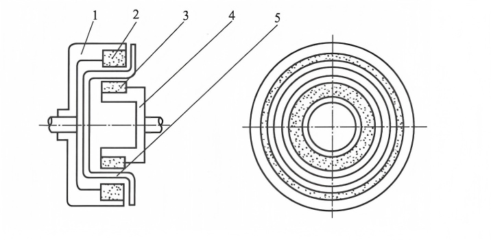
Gambar 1-29 Diagram Skematik Struktur Penggerak Magnetik Silindris
1—Rotor luar; 2—Baja magnetik luar; 3—Baja magnetik dalam; 4—Rotor dalam; 5—Selongsong isolasi
Ketebalan selubung isolasi berkaitan dengan tekanan kerja dan suhu operasi. Jika terlalu tebal, celah antara magnet dalam dan luar akan meningkat, yang akan memengaruhi efisiensi penggerak magnetik. Jika terlalu tipis, kekuatan akan terpengaruh. Ada dua jenis selubung isolasi: logam dan non-logam. Selubung isolasi logam memiliki kehilangan arus eddy, sedangkan selubung isolasi non-logam tidak memiliki kehilangan arus eddy.
⑥ bantalan selongsong
Poros pompa sentrifugal yang digerakkan secara magnetis ditopang oleh bantalan geser. Karena bantalan geser bergantung pada media yang diangkut untuk pelumasan, bantalan tersebut harus dibuat dari bahan dengan ketahanan aus yang sangat baik dan sifat pelumasan sendiri. Bahan bantalan yang umum digunakan meliputi silikon karbida, keramik, bahan berbasis grafit, dan komposit berisi politetrafluoroetilena (PTFE).
Pelumasan bantalan geser bergantung pada aliran fluida internalnya sendiri, yang mengharuskan bantalan, bushing, dan cakram dorong memiliki sifat pelumasan mandiri, ketahanan aus, dan ketahanan korosi yang sangat baik. Misalnya, SSiC dan YWN8 menunjukkan ketahanan aus, ketahanan korosi, dan sifat pelumasan mandiri yang luar biasa, dengan SSiC memiliki kekerasan relatif yang lebih tinggi daripada YWN8. Ketika dipasangkan dengan bantalan dorong, kombinasi material lunak dan keras membentuk pasangan gesekan yang optimal, secara signifikan memperpanjang masa pakai bantalan. Uji praktis telah menunjukkan bahwa masa pakai bantalan yang dipasangkan yang terbuat dari material ini (SSiC dan YWN8) dapat hingga 10 kali lebih lama daripada bantalan grafit atau bantalan SiC yang dipasangkan dengan material yang sama. Sebagai komponen penting dalam pompa magnetik, memperpanjang masa pakai bantalan geser secara langsung meningkatkan masa pakai keseluruhan pompa magnetik. Oleh karena itu, pemilihan material sangat penting untuk memastikan pengoperasian pompa magnetik yang stabil dan jangka panjang.
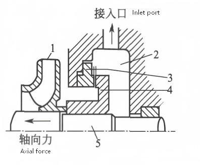
⑦ penyeimbang
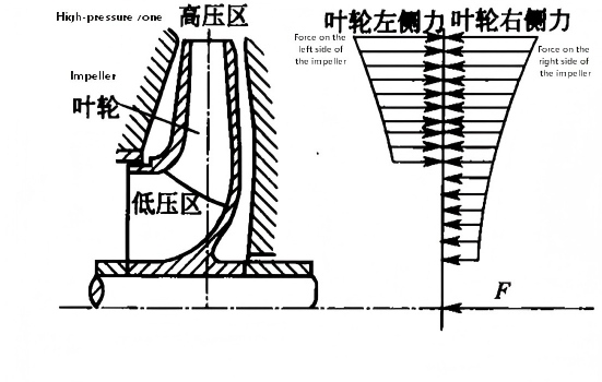
Pada pompa yang digerakkan secara magnetis, gaya yang bekerja pada kedua sisi impeler tidak sama, seperti yang ditunjukkan pada Gambar 1-30. Ketika pompa dihidupkan sesaat oleh mekanisme penggerak, gaya aksial diberikan pada impeler ke arah sisi hisap. Jika gaya aksial ini tidak dihilangkan, gerakan aksial bagian yang berputar akan terjadi, yang menyebabkan keausan, getaran, dan panas berlebih, sehingga mencegah pompa beroperasi secara normal. Oleh karena itu, alat penyeimbang harus digunakan untuk mencegah gerakan aksial. Jenis alat penyeimbang aksial yang paling umum meliputi lubang penyeimbang, pipa penyeimbang, dan cakram penyeimbang.
a. lubang keseimbangan
Cincin penyegel yang sama ditambahkan ke penutup belakang impeler, dan beberapa lubang dibuka pada penutup belakang (lubang penyeimbang) untuk membuat tekanan pada penutup belakang sama dengan tekanan masuk hisap, sehingga menyeimbangkan gaya aksial.
b. pipa penyeimbang
Sebuah pipa terhubung ke badan pompa dan mengarah ke saluran masuk hisap, memastikan keseimbangan tekanan di kedua sisi impeler. Kedua perangkat ini memiliki struktur sederhana tetapi dapat menyebabkan aliran balik cairan, mengurangi efisiensi. Selain itu, 10%-25% dari gaya aksial tetap tidak seimbang, yang biasanya membutuhkan cakram dorong untuk menyerap gaya aksial residual.
c. cakram penyeimbang
Gambar 1-31 mengilustrasikan skema rakitan cakram penyeimbang, yang terutama digunakan dalam pompa multi-tahap Di mana ia terpasang pada impeler tahap akhir pada poros yang sama. Terdapat celah aksial antara cakram penyeimbang dan badan pompa. Selama pengoperasian, cairan bertekanan tinggi mengalir melalui celah ini ke ruang penyeimbang di sisi kanan cakram penyeimbang. Ruang penyeimbang terhubung ke saluran masuk hisap, menjaga tekanan tetap sama. Ini menciptakan perbedaan tekanan di seluruh cakram penyeimbang, dengan gaya dorong dan gaya aksial yang berlawanan saling menyeimbangkan. Komponen berputar pompa dapat bergerak secara lateral, dan cakram penyeimbang secara otomatis mempertahankan keseimbangan selama pengoperasian. Selain itu, metode seperti menggunakan impeler hisap ganda atau impeler yang disusun simetris juga dapat membantu menyeimbangkan gaya aksial parsial.
Gambar 1-31 Diagram Skematik Perangkat Cakram Keseimbangan
1—Impeller tahap akhir; 2—Ruang penyeimbang; 3—Jarak aksial; 4—Cakram penyeimbang; 5—Poros pompa


 IPv6 network supported.